In this tutorial, you will learn how to create the “clay” and wire frames commonly used to display models. Apart from looking cool, they allow you to see curves and corners more clearly by the use of light and shadows. Key terms include Light Tracer, Skylight, Mental Ray Final Gather, Bounces, Composite and wire materials. This tutorial is aimed at the beginner and every step is outlined and displayed in detail. If you are entirely new to 3D Studio MAX, you may want to try some of our other tutorials first.
Create a clay render using the default 3D Studio MAX renderer
Step 1
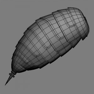
Start a new scene in 3D Studio Max and add a model to the scene. Use one of your own models, download one from our Models section, or you can simply add a primitive such as a sphere. I am going to use the back end of a robot wasp.
Step 2
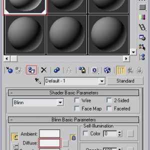
Open the Material Editor from the Rendering menu (or press the M key) and assign the first default material to your object. Click on the Diffuse color of the material and set it to white, or almost white if you want.
Step 3
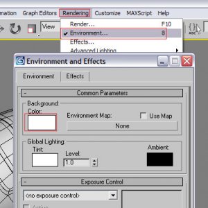
Select Environment from the Rendering menu (or press the 8 Key) and set the Background Color to white (or close). Close the Environment and Effects window.
Step 4
Add a Plane primitive to the scene and scale it up until it covers the entire floor. Just make it big, very big. From the Left or Front viewport, make sure the Plane is directly below your primary object.
Assign the same white standard material to the Plane as you did with the main object.
Step 5
Place a Skylight in the scene on the Top viewport and move it up on the Left or Front viewport. Its eventual location does not matter much.
Step 6
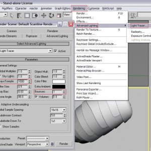
Select Light Tracer from the Advanced Lighting option in the Rendering menu. You could do a quick render now so see how it turns out, but if you have a fairly fast computer, you should tweak some settings in the Parameters section of the Advanced Lighting tab.
For example, set the Rays/Sample option to 1000 and the Bounce option to 1. For even better results, increase the Filter Size to 2 for example, and the Sample Size to 8×8 or 4×4.
Step 7
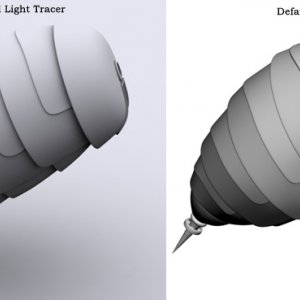
When you render the image (press F10/ Render button), it should turn out similar to the following.
Save this scene as WIPimg_LT.
Create a clay render using the the Mental Ray renderer
Step 1
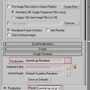
We are going to use the same scene as above, but a different renderer: Mental Ray. I’m going to use a different, more simple, model for this part but you can just continue with the scene saved in the previous step. There is no need to turn of the Light Tracer option because it is not available when using Mental Ray anyway.On the Render Scene dialog box (Press F10 or select Render from the Rendering menu to open it), on the Common tab in the Assign Renderer section, choose Mental Ray as the renderer for Production images. Or, select mental.ray.no.gi.high from the Preset menu.
On the Renderer tab, make sure the Samples per Pixel Minimum is at least 1 and Maximum is at least 16.
Step 2
On the Indirect Illumination tab, enable the Final Gather option.Using Mental Ray for renders like this usually requires a bit more time, so you may want to lower the Samples value to 500 or 250 if it takes too long for your taste. If you have a dual Pentium with HyperThreading support for example, feel free to increase it.
Final Gather also offers a Maximum Bounces option in the Trace Depth section, similar to Light Tracer’s Bounces option. Setting it to 1 can improve the results, but if you do, you may want to change the main material on your object and the ground plane and make them a bit darker instead of completely white.
Step 3
Click the Render button. Final Gather Points will be computed before the actually rendering starts. The result should be similar to my image. If you look carefully, you’ll see some weird ‘artifacts’ in the lower creases. The image can be improved by using more Samples, a higher filter value, and using global illumination. However, this is a WIP image and these additional settings result in additional render time.
Create a clay render with wireframe using the Mental Ray renderer
Step 1
Mental Ray takes a bit longer to render clay images but there is an advantage to using MR: you can render the clay object including the wireframe in a single pass. We are going to continue with the same scene from the previous step.
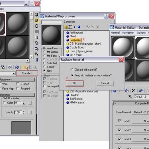
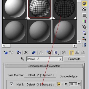
Open the Material Editor and assign the second default material to your object. Click the Diffuse color and set it to white again. Click the Standard button in the Material Editor and choose Composite. Keep the current material as a sub-material when asked.
Step 2
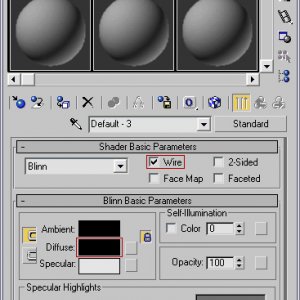
Select the third default material and set its Diffuse color to black. Enable the Wire option.
In the Extended Parameters section, decrease or increase the Wire Size, set it to 0.7 or 1.5 for example. You may need to play around with this setting later to get the best results. This depends on the geometry and scale of the model and the size of your render. Leave it at 1 if you are not sure.
Step 3
Click on the second material in the Material Editor (the white standard material you assigned to your object in step 1) and drag the third material (the black wire material) to the Mat. 1: slot. Choose Instance instead of copy when asked in the small dialog box.
If you have a highly detailed and smoothed model, consider enabling the Display Isolines option in the MeshSmooth or TurboSmooth modifier settings. This allows you to render the model smoothed and show only the original, but also smoothed, wireframe.
Step 4
Press F10 to open the Render Scene dialog and click the Render button. The image should turn out similar to the following.

Create a good wireframe image
Step 1
Sometimes you just want to post a simple wireframe image to show off your loops. Some quick adjustments before making your screenshots look good.
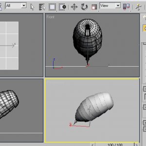
First, assign a white material to the object (like we did in the previous parts). Select your object(s), and set the Object Color to black as depicted in the image.
Step 2
If you have a MeshSmooth or TurboSmooth modifier on your object(s), turn them off.
Go to Polygon sub-object level, select all the polygons of the object (ie. select one polygon and press CTRL-A), and Clear All smoothing groups for the entire object.
Step 3
Now deselect the objects. I.o.w. make sure nothing is selected. Hide or delete the ground plane.Now press the Print Screen button on your keyboard and paste the results in Photoshop or similar, and cut out the part you want to save and shows as a WIP image.
The result should be similar as in the following image:

