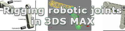
Like most tasks in 3D Studio Max and similar products, rigging robots is easy, if you know how. Depending on the complexity of the robot, some may find it even easier than rigging a human or animal character. This is because most parts of a robot do not deform during movement, with the exception of cabling and other flexible parts, so you don’t have to ‘skin’ it. One of the primary challenges in building a cool robot, which still looks cool when animated, is creating realistic mechanical joints.
The first version of our example robotic leg below is not very realistic however, because it would collapse like a bone structure without muscles. In the second version, we will add some robotic ‘muscles’, and the third version will include a hose. Click on the download links below some of the pictures to download the corresponding scene.
1. A Human Leg
When rigging a human leg, the mesh deforms when the knee bends, pushing vertexes away from each other on one side and towards each other on the opposite side. This is accomplished by using a Skin modifier that binds vertexes of the mesh to the bones. The colors of the vertexes indicate the weight values which dictate how much influence moving the joint will have on those vertexes. Red vertexes represent the most rigid parts.
2. Our Example Robot Leg
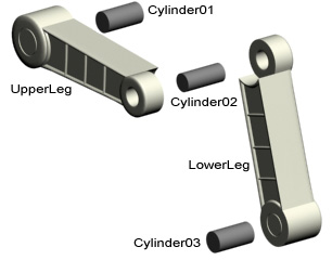
Robots are typically made of metal, plastic, or some other hard and rigid material that does not deform. The following picture shows the five objects that form the basis of our example leg.

3. Rigging Our Example Robot Leg
As usual, I have to make a note that the following is just a way of doing this, which doesn’t necessarily means it is the way (we’ll actually show another way later on). Picture 3a below shows the (unsmoothed) wireframe of the objects that make up this leg. Click the link below it to download the scene, or download the scene including the bones by clicking the link below Picture 3h, or just watch the pictures if you do not feel like actually doing any of this right now.
 Picture 3a.
The red dots in the picture above represent the pivot of the object. In the scene you can download, I have already moved them to the correct position. The UpperLeg’s pivot is positioned at exactly the same position as the pivot of Cylinder01, and LowerLeg’s pivot is at the same position as the pivot of Cylinder02. When switching to the top view, they are all aligned. It is essential that the bones you add start or end exactly at those pivot points.
A way of making sure the bones are positioned correctly is to snap to pivots. When you use this method it is also essential that all the pivots are aligned when viewing from the top. If in your robot they aren’t and it is too complex or difficult to align them, you can skip the following snap settings and just draw the bones, select them all and move them to the center of the leg (Top view). To use the snap setting, right-click the Snaps Toggle button on the main toolbar and select Pivot and clear others if necessary (see Picture 3b). Now click the Snaps Toggle button again (with the left mouse button) to enable it.
 Picture 3b.
Click the Bones button in the Systems section on the Create tab of the Command Panel as displayed in Picture 3c below. Choose SplineIKSolver as the IK Solver and enable Assign to Children (you can use another IK Solver or none at all, if you prefer).
 Picture 3c.
Now draw the bones, by clicking on the spots 1, 2, and 3 shown in Picture 3d and then right-click anywhere in the viewport to stop. Spots 1, 2 and 3 are the pivot points of Cylinder01, Cylinder02, and Cylinder03.
 Picture 3d.
When the Spline IK Solver dialog shown in Picture 3e below opens, just click OK.
 Picture 3e.
Now before you link the bones to the leg, you should make sure that the pivots of the bones are positioned correctly on the pivot of the limbs, the Spline IK Solver we added moved them slightly. To move a bone’s pivot, click the Affect Pivot Only button on the Hierarchy tab of the Command Panel, and disable the Enabled button on the Motion tab of the Command Panel.
 Picture 3f.
Then select the pivot of the bone and move it to the correct position. Make sure you zoom in and place it exactly in the center of the limbs’ pivots. You also might want to disable the snap to pivot setting first by clicking the Snaps Toggle button again. If for some reason you cannot get them in the right position, there is no need to continue, as the whole setup depends on the pivots’ position.
When you are sure the pivots are positioned correctly, select Cylinder01 and link it to UpperLeg. Select Cylinder02 and link it to the LowerLeg, and select Cylinder03 to LowerLeg as well. To link one object to another click the Select and Link button on the main tool bar, select the object you want to link and drag to the object you want to link to. If you do it correctly, the object you link to, will flash white once.
We will use the same select and link method to link the objects to the bones, instead of using a Skin modifier. Link UpperLeg to the upper bone, and link LowerLeg to the lower bone.
 Picture 3g.
When you done all of the above, or download the scene including the bones by using the link below, select the IK Chain or any of the point helpers and move it. The knee joint should now operate as shown in Picture 3g, without any of the objects deforming during movement.
 Picture 3h.
4. Another Approach
Before we continue with this leg and add some muscles, we will use another method of rigging this leg. As someone kindly pointed out to me, there is no absolute need to use bones . If you are new to rigging characters or robots in particular, you may want to go for the bones method discussed above, but a robot is often a skeleton by itself, eliminating the need for bones. 3D Studio Max allows any object to act like a bone, and allows you also to assign IK solvers to any hierarchical set of objects. Also in this type of ‘bone’ setup, it is absolutely imperative that the pivots of the objects are in the correct position. We will illustrate this with some pictures later.
To make this work with the previous example (delete the previous bone structure or use the scene you downloaded earlier), and link the objects to each other as followed:
Cylinder03 -> LowerLeg LowerLeg -> Cylinder02
Cylinder02 -> UpperLeg
UpperLeg -> Cylinder01
Press the Schematic View (Open) button on the main toolbar to check if the hierarchy is now correct as displayed in Picture 4a.
 Picture 4a.
Now all you need to do is add an IK Solver to this hierarchy to make it act like a robotic leg. You can use the IK Solver you prefer, but in this example, we are going to use the History Independent solver. Select Cylinder03, choose HI Solver from the IK Solvers section in the Animation menu, and select Cylinder01. To prevent you from linking the solver to UpperLeg instead of Cylinder01, use the Select by Name option, which basically means you should press the H key on your keyboard after you choose HI Solver from the menu, and then pick Cylinder01 from the list, instead of clicking on it in the viewport.
If you performed the previous tasks correctly, the results should be like in Picture 4b with the IK Chain selected. If you move the IK Chain the leg should work. To make the task of animating this leg a bit more convenient, you should link the IK Chain to a Point Helper.
A Point helper can be created by clicking the Point button in the Helpers section of the Create tab on the Command Panel, and clicking somewhere in the viewport, as depicted in Picture 4b below. In this case, I suggest you place it somewhere at the bottom of the leg. Use the same Select and Link method as discussed earlier to link the IK Chain to the Point helper, so you can animate the leg by moving the Point helper.
 Picture 4b.
If your robot has a complex geometry and animating the individual objects slows down your computer too much, you can configure 3D Studio Max to display the objects as bones. When using our example leg from the previous steps, you should select Cylinder01, 02, 03, UpperLeg, and LowerLeg, and select Bone Tools from the Character menu. Enable the Bone On option on the Bone Tools dialog as shown below.
 Picture 4c.
Next, open the Display tab on the Command Panel, scroll down, and in the Link Display section enable the Display Links option and the Link Replaces Object option.
 Picture 4d.
The results should be as depicted in Picture 4e below.
 Picture 4e.
Alternatively, you can enable only the Display Links option and right above the Link Display section enable the Display as Box option in the Display Properties section. The results should be as depicted in Picture 4f below.
 Picture 4f.
5. Muscles
As I mentioned earlier, the leg used in the example above is not very realistic; it needs some muscles to make it move automatically and at the same time give it some strength. You can make up your own mechanisms, but you can also use one of the three main methods used in modern real world robots:
Electrical motors
For the example leg from above, this would be the easy way out, as you would ‘only’ have to increase the size of the knee joint and modify it into to something like shown below in Photo I, so it becomes viable an electrical motor could fit inside. Additionally, rigging the robot is easy as you can use one of the methods we discussed earlier.
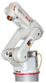 Photo I. Industrial robot arm powered by electrical motors.
Hydraulic/Pneumatic/Magnetic pistons
Another commonly used method to power robots are pistons. A piston (see Photo II below) is basically consists of a metal bar that goes inside a tube. Pressurized air or oil is pumped into the piston to push out metal bar. This is usually the sound you here when a robot moves. If you want to make them realistic, you should attach a hose to it, which leads to a compressor somewhere in or on the robot. These hydraulic or pneumatic pistons are much more powerful than electrical motors. Smaller pistons may use magnetic force to either pull or push the metal bar. The latter would have electrical wires attached to it, instead of a hose.
 Photo II. Crane powered by hydraulic pistons.
Picture 5a and 5b show our second example leg. It includes a piston that is made of two cylinders called Piston_PA and Piston_PB. Two additional cylinders (P_Axis_A and P_Axis_B) form the axis of the piston’s parts.
 Picture 5a. & Picture 5b.
As you can see in Picture 5c below, we already rigged the leg with two bones and an IKSplineSolver. You can download the scene by clicking the link below the picture.
 Picture 5c.
First, we will link the piston’s parts to the leg as followed:
P_Axis_A -> UpperLeg P_Axis_B -> LowerLeg
Piston_PA -> P_Axis_A
Piston_PB -> P_Axis_B
The hierarchy of the leg should now be exactly like in Picture 5d.
 Picture 5d.
If we would bend the knee, by using the lower helper (Point3) for example, the two parts of the piston will not stay aligned correctly and will ‘break’ as shown in Picture 5e below.
 Picture 5e.
(If you moved the leg, press use Undo (Ctrl-Z) to move it back to its original position.)
To make sure the metal bar stays inside the tube, we need to use a constraint, in this case the Look At constraint. As in the previous parts of this tutorial, the placement of the pivots of the piston’s parts is essential to make it work. The pivots for P_Axis_A and Piston_PA are exactly on the same position, and the pivots for P_Axis_B and Piston_PB are also exactly on the same position. We have already done this in the downloadable scene by selecting the parts that have the pivots on the same axis, enabling the Affect Pivot Only button (see Picture 3f) and using the Align tool (on both the Front, Top, and Left view).
We will need to add two Look At constraints, one for each part of the piston. Select Piston_PA and select Look At from the Constraints section in the Animation menu, as depicted in Picture 5f below.
 Picture 5f.
Press the H key on your keyboard, select P_Axis_B, and click the Pick button. Piston_PA now changes its orientation. To make sure it point in the original direction, enable the Keep Initial Offset option on the Parameters section on the Motion tab of the Command Panel, as depicted in Picture 5g below. (The parameters section opened automatically when you added the Look At constraint.)
 Picture 5g.
Repeat this step for the other part of the piston, in other words: select Piston_PB, select Look At constraint from the Animation menu, pick the P_Axis_A as the target (using the H button to pick it). Also enable the Keep Initial Offset option again. So what we did is make one part of the piston ‘looks at’ the opposite part’s axis. The orientation is depicted with a blue line. If you select the helper Point03 and move it again, you will see that the metal bat slides neatly into the tube, as shown in Picture 5h below.
 Picture 5h.
To make it more realistic, we need to attach a pipe or hose to the hydraulic or pneumatic piston, and we need to make sure it moves and/or bends when the leg moves. There are many ways of doing this, but a relatively easy one is to use the extended primitive Hose. The advantage of using the Hose primitive is that you don’t need to rig it; no bones, and no IK. Instead, we are going to add two extra Cylinders, in addition to the Hose, and let the Hose start and end at those cylinders.
In Picture 5i below you can see where we placed the two cylinders. The cylinder on the left is linked to UpperLeg, and the other is linked to Piston_PA. These cylinders represent the entry points of the hose, or the connector of a wire for example. You will probably want to use something more sophisticated than a cylinder, but make sure it is a separate object.
 Picture 5i.
Next, create the hose by selecting Extended Primitives on the Create tab of the Command Panel, clicking the Hose button, and drawing a hose in any viewport, as shown in Picture 5j below. Don’t worry about its size, location, or shape yet.
 Picture 5j.
On the Modify tab of the Command Panel, enable the Bound to Object Pivots. Click the Pick Top Object button and click on the left cylinder. Click the Pick Bottom Object button and click on the right cylinder (or use the H key on your keyboard).
 Picture 5k.
Depending on the orientation of the cylinders we use to connect the hose and the viewport you created them on, you may have to rotate the pivot of one or both cylinders. So if necessary, select the cylinder, enable the Affect Pivot Only button (picture 3f), and rotate the pivot. While you rotate the pivot, the hose will bend with it so you can easily see when it is at the right angle.
When the hose is correctly aligned to the cylinders, click the hose again, scroll down below on the Modify tab, and disable the Flex Section Enable option as shown below in Picture 5l. Also decrease the Diameter: value in the Hose Shape section to a value that is less than the cylinders.
 Picture 5l.
As you can see, the hose is too long and needs to hang more tightly against the leg. You can do this by decreasing the Tension values (see Picture 5k). In the final images below, we used 25 for both cylinders. If you move the leg again using on of the helpers, you will notice that the hose will stay in position and even bend when it has to. Click on one of the images to see the final animation.
 Picture 5m.
Download the final scene here.
I hope you enjoyed this tutorial and that it contributed something to your 3D Studio Max modeling skills.